

Sensing the Way Forward
Read the latest from Patrice Flot, Chief Technical Officer at CMR Group on the recent history and future of industrial engine temperature sensors for High Horsepower applications. This article was published in the December 2015 issue of Shipping and Marine.
Download the article here:- Sensing the Future – Marine and Shipping Dec 2015.pdf
OEM’s building engines for a wide variety of industrial and commercial applications are ramping up electronic technologies in order to stay competitive. Electronic component reliability is become increasingly well proven, allowing for better configuration and higher performance of advanced engines.
Better sensor reliability reduces the risk of instrumentation failure, but the expanded use of advanced sensors is increasing the costs of measurement and monitoring systems compared to other engine components.
Temperature sensors are usually the most costly and numerous sensor type, often found at several locations on the same engine circuit, measuring a range of parameters including oils, fuels, water, gases and exhaust.
Temperature monitoring at critical engine locations provides important information on running behaviour, safety margins and the need for maintenance on critical components like cylinder liners, exhaust valve seats and bearings. Even mobile parts of the gear train can be monitored for temperature thanks to wireless technology. Excessive temperature values and gradients could be an early indicator of imminent component failure.
The three established sensor technologies of thermocouples, resistance temperature detectors (RTD) and thermistors are often combined on the same engine, each with their own advantages and drawbacks.
THERMOCOUPLES
Thermocouples have a high temperature capability ideal for measuring exhaust gases, cylinder head outlet, and turbocharger temperatures. They can also be used on fluids and engine components such as bearings, liners or exhaust valve seats when short response time is of interest and unobtrusive design is required.
Thermocouples give the shortest response times due to a small thermal inertia. They also offer the smallest size intrusion and are very robust against vibrations and thermal shocks. The drawback however is with accuracy as the relationship between temperature and voltage is not linear and depends on material quality and purity. This can be kept under control thanks to standards like CEI 60584-1.
Another disadvantage is related to installation cost. Thermocouples are required to compensate for the ‘cold junction’ by using a compensation cable, made of cheaper materials than the thermocouples themselves, so that no parasitic Peltier effect occurs at any cold junction connections along the wires. Compensation is sometimes managed by using additional temperature measurement in the junction box. Other drawbacks are found in the electronics as the lower voltage needs to be amplified to a few volts to allow reading on standard human-machine interfaces (HMI).
RTD’S
RTD’s mostly employ platinum elements and are used either at PT100 or PT1000, but seldom as PT200. In this designation, the number following letters ‘PT’ indicates the ohms value at 0°C. These are electronic resistances that show resistance value depending on their temperature according to a linear curve; higher temperature goes with higher resistance.
RTD’s are low cost and accurate, typically adhering to CEI-6075 standard. Also, extension cables for connection to the HMI use low cost copper lines. PT100 continues to be popular for fluid temperature measurement, but needs to be connected by three or four wires to get the required accuracy. However, PT1000 sensors are becoming increasingly prominent as connection line resistance is comparatively negligible and does not affect accuracy.
Sturdy sensor housing and installation for RTD’s are highly important as the platinum element can be sensitive to vibrations. RTD sensors are mainly used for fluids, compressed air and bearings as high temperature measurement in the region of 600°C is limited and response times can slow due to thermal inertia.
Whilst their lead-wire resistance does not affect sensor accuracy, thermistors are sensitive to temperature, typically having much higher nominal resistance values than RTDs. These low cost ‘ready for use’ electronics are often used in automotive applications. However, not all automotive sensors can be used on industrial engines, which use much larger pipes and tubing than automotive engines.
For example, industrial engines with 4000 hours of operation represents only around nine months of running. For cars however, 4000 hours of running will bring them close to the end of their life cycle. With time between major overhauls for industrial engines varying from 30,000 to 50,000 hours, it is a challenge for fragile sensors to last this long with heavy day-to-day use.
Instrumentation manufacturers are beginning to work with engine OEM’s to develop solutions to meet the reliability and lifetime challenges for industrial engine sensors, whilst trying to minimise engine delivery cost. Attempts have been to develop cheaper RTDs and thermistors that have higher temperature tolerances, rather than relying on expensive thermocouples.
TYPE K (TK)
In the early 2000’s, some engine OEM’s decided to replace Type K (TK) thermocouples in large engines with thermistors and PT1000 sensors, developed from existing automotive or industrial sensors. Despite intensive qualification tests, this conversion resulted in too many operational failures, leading to expensive recalls.
Two to three years were necessary to overcome these R&D issues, so engine OEM’s returned to using adapted TK sensors with signal convertors, compatible with existing RTD electronics. At CMR, we postponed the launch of our new PT1000 sensors for a few years until our development and testing programme produced the safe solutions with reasonable lifetimes required by our customers.
The evolution of engine technology makes the importance of reliability and long lifetime for exhaust gas temperature sensors increasingly critical. Before turn of the millennium, sensors for exhaust gas, injectors, fuel pump status and other engine health indications were optional or unnecessary for smaller engines. Even on larger engines, exhaust gas sensor failure would not stop the engine itself, but just provide a warning.
As reliable sensors are now mandatory for today’s common rail and electronic gas engines, such sensor failures, even for a few milliseconds, are unacceptable. Any failure on exhaust gas temperature sensors will now lead to the immediate shut down of the engine.
Exhaust gas temperature sensors are now mandatory for smaller engines with electronic injection, offering considerable business opportunities to a few instrumentation makers that are able to produce sensors with excellent reliability. This situation will not last forever. New alternatives have been developed since 2010 to overcome the weaknesses of low cost PT1000 sensors by incorporating sought after features such as fast response time, long lifetime, vibration resistance, high temperature reliability, small diameter and low wiring and integration costs.
SMART J1939 SENSORS
These solutions use miniaturised electronic convertors attached to each sensor, transforming analogue signals to digital ‘CAN’ protocol, conforming to ISO 11898 and SAE J1939 standards. Also, a simpler measurement harness, reduced to four wires instead of dozens, can be directly connected to the HMI using only one standardised port dedicated to digital input, relegating the need for an HMI acquisition box.
CMR performed a cost estimate simulation for engines traditionally fitted with expensive TK thermocouples on exhaust gas cylinder heads and turbochargers. These and all other sensors were changed to CMR’s J1939 Connect CAN sensor, which uses J-SENSETM technology. Our findings showed that while wires and mechanical parts are cheaper, when electronics cost is similar, total cost can be significantly lower with digital sensor system.
Builders of advanced digital protocol engines with electronically injected fuels can embrace this digital technology expansion and will benefit from cost advantages and the reliability gained through rigorous testing and qualification programs.
Even though multiple digital sensors located on same CAN line need a specific address for each individual sensor, the sensor still retains the same address; even after refurbishment/installation as the same type of sensor is consistently installed between cylinder heads.
This does not seem to be a significant obstacle, since most engine end users are industrial organisations that have extensive experience in dealing with automation systems and device management. They can be confident that sensor manufacturers will provide easy maintenance and management tools for engine manufacturers and end-users, similar to what we see at home in domestic automation systems.
Engine builders are recognising the flexibility advantage of digital technology that allows fast implementation of additional sensors, without any physical change in input/output ports of the Engine Control Unit (ECU), allowing additional reserves of sensors imbedded in the ECU. The complexity of harness design is also reduced as any additional sensors simply require an additional harness connector, without an increase in harness size or additional wiring.- See more at: http://www.cmr-group.com/world-news/sensing-the-way-forward#sthash.eeQh0CHr.dpuf
CMR Launches Full Vessel Management System (FVMS) capability
CMR is showcasing its FVMS capabilities at two key 2015 marine tradeshows – Kormarine, Busan (Oct 20-23) and Marintec, Shanghai (Dec 1-4).
The company is building upon the launch of its advanced Integrated Alarm Monitoring Control System (IAMCS) in 2014 by developing a state-of-the-art turnkey Full Vessel Management System (FVMS) for ships of all sizes – from small craft such as tugs, workboats and private build pleasure crafts through to medium-sized commercial vessels such as ferries, PSV’s cargo ships and ocean going yachts.
Recently implemented on a 180m passenger ferry built at Brodosplit Shipyard in Croatia, CMR’s FVMS protects the value of engines and fleets with reliable, high-quality electrical and electronic systems that integrates other types of marine electronics including low voltage/main switchboards, fire detection and CCTV.
Gerard Baldellou, Marine Division Manager at CMR Group said,
“By interconnecting these devices in advantageous combinations, energy consumption can be reduced, operational efficiency of the engine can be improved and redundancy can be provided in the event that oneor more components are disabled”.
CMR’s new system also includes a marine propulsion system with many different combinations and interconnections between one or several engines, generators, electrical systems, clutches, marine propulsion devices and an electrical storage device.
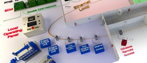
Our marine product range covers FVMS, IAMCS, Power Management, Local Operating Panels/Engine Vision, engine safety, data acquisition/processing, cabling, sensors, display units and workstations. CMR also has experience and expertise in many ancillary systems such as Fire Detection Systems (FDS), HVAC, Ballast Water and Feed Water.
IAMCS offers a powerful microprocessor-based system that reads output data using CANopen and J1939 protocols while operating with an intuitive Supervision System and human to machine interface (HMI). This provides all necessary functions for protection and control adherence to Unattended Machinery Space (UMS) marine notations.
These Marine Society approved systems are certified by bodies that include Lloyd’s Register (LRS), Det Norske Veritas (DNV), Bureau Veritas (BV) and American Bureau of Shipping (ABS).- See more at: http://www.cmr-group.com/world-news/full-vessel-management-systems#sthash.H1YxdoJ3.dpuf

Triple Mexican Marine Order for CMR & PDI
*Picture – CMR Group and PDI Berimar during acceptance testing in Marseille, November 2015
Working with Spanish marine agent and automation specialist PDI Beiramar, CMR is installing complete CLARINUXTM Integrated Alarm, Monitoring and Control System (IAMCS) installations for 3 large tug boats based in Mexico.
Gerard Baldellou, Marine Division Manager at CMR Group said: “In the highly competitive vessel automation sector, our global customers are benefitting from excellent service support through PDI Beiramar who are able to deliver and integtrate robust CMR systems that utilise robust hardware and flexible intuitive CLARINUXTM software.”
The integrated alarm, monitoring and control system (IAMCS) has the following subsystems:
ALARM SYSTEM
- Hardware channels: 200 on/off channels and 100 analogue channels (4-20mA, Pt100 and NiCrNi).
- Software channels: 1 Modbus communication with PMS in order to send and receive data.
- Alarm Groups: Alarm Groups.
CONTROL SYSTEM
- 4 stand-by pumps:8 start/stop pumps.
- M.E.1 Lub. Oil stand-by pump
- M.E.2 Lub. Oil stand-by pump
- M.E.1 Fresh water stand-by pump
- M.E.2 Fresh water stand-by pump
- 68 double effect valves (open/close):
- 28 for ballast and bilge system.
- 40 for diesel oil system.
- I/O points: 176 DI and 172 DO
ENGINEER REPEATERS AND DEAD MAN SYSTEM
- Repeaters: 1 Repeater for Bridge, 1 Repeater for ECR for ER manned/unmanned, 4 Repeaters for cabins (3) and mess (1)
- Dead Man Alarm: 2 On/Off units and 2 Reset units. These units will be mounted in the E.R.
P.M.S
- Electric Plant: 440vac, 60Hz.
- Equipment to control: 2 Auxiliary generators, 500kVA each, 4 Heavy consumers
– See more at: http://www.cmr-group.com/world-news/mexican-marine-order-for-cmr-and-pdi#sthash.cLxnfJWa.dpuf